
Modify PWM through button presses
Learn to control LED brightness using Pulse Width Modulation (PWM) by button presses on a Raspberry Pi
Written by: Jonathan Tynan
Last updated: May 11 2025
In this tutorial, we bring all the previous lessons together. We are reading button presses and will use these readings to modify the brightness of an LED by changing the PWM duty cycle. This tutorial brings together digital pin reading, writing and PWM modification. This is a simple demonstration of how to integrate various physical components and get them working with each other.
Components
Section titled “Components”See Blink LED Tutorial for more details on these components.
- Breadboard
- LED
- 220 Ω Resistor
- Jumper Wires
See Read Button Press Tutorial for more details on these components:
- 2 Push Buttons
The Circuit
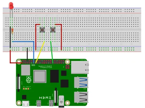
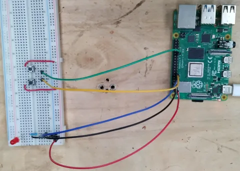
Section titled “The Circuit”Below we can see the circuit diagram for this project. First we have the Raspberry Pi ground connected to the ground rail of the breadboard and a 3.3V pin connected to the power rail of the bread board. We then have an LED which is connected to the ground rail and to Pin 11 through a 220 Ω resistor. Next we have 2 buttons, where both are connected to the powered rail on the breadboard and the otherside of the buttons are connected to pins 13 and 29.
The Code
Section titled “The Code”Below is an example program that will detect button presses to increase or decrease the brightness of an LED.
#include "splashkit.h"
int main(){    int brightness = 128;    const int max_brightness = 255;    unsigned long last_read_time = 0;    const unsigned long read_interval = 400;
    raspi_init();    gpio_pin led_pin = PIN_11;    gpio_pin increase_btn_pin = PIN_13;    gpio_pin decrease_btn_pin = PIN_29;
    raspi_set_mode(led_pin, GPIO_OUTPUT);    raspi_set_pwm_dutycycle(led_pin, brightness);
    raspi_set_mode(increase_btn_pin, GPIO_INPUT);    raspi_set_mode(decrease_btn_pin, GPIO_INPUT);
    raspi_set_pull_up_down(increase_btn_pin, PUD_DOWN);    raspi_set_pull_up_down(decrease_btn_pin, PUD_DOWN);
    timer run_timer = create_timer("run_timer");    start_timer(run_timer);    unsigned long current_time = 0;
    open_window("dummy_window", 1, 1);    while(!any_key_pressed())    {        process_events();        current_time = timer_ticks(run_timer);        if(current_time - last_read_time > read_interval)        {            if(raspi_read(increase_btn_pin) == GPIO_HIGH)            {                brightness += 25;                if(brightness > max_brightness)                    brightness = max_brightness;                raspi_set_pwm_dutycycle(led_pin, brightness);                last_read_time = current_time;            }            if(raspi_read(decrease_btn_pin) == GPIO_HIGH)            {                brightness -= 25;                if(brightness < 0)                    brightness = 0;                raspi_set_pwm_dutycycle(led_pin, brightness);                last_read_time = current_time;            }        }    }
    close_all_windows();    stop_timer(run_timer);    free_all_timers();    raspi_cleanup();    return 0;}
Understanding the code
Section titled “Understanding the code”Okay, now lets break down this code and look at its sections.
-
Initialise Values:
Firtly, we set up the variables that we’re going to need:
brightnessis given an inital value of 128 which is 50% of our maximum, 255.last_read_timeis set to 0 andread_intervalis set to 400.We are using this to implement a simple debounce technique, in which we wait a short period of time (the interval), in a non-blocking manner, to make sure the pushbutton is definitely pressed.
#include "splashkit.h"int main(){int brightness = 128;const int max_brightness = 255;unsigned long last_read_time = 0;const unsigned long read_interval = 400;raspi_init();gpio_pin led_pin = PIN_11;gpio_pin increase_btn_pin = PIN_13;gpio_pin decrease_btn_pin = PIN_29;raspi_set_mode(led_pin, GPIO_OUTPUT);raspi_set_pwm_dutycycle(led_pin, brightness);raspi_set_mode(increase_btn_pin, GPIO_INPUT);raspi_set_mode(decrease_btn_pin, GPIO_INPUT);raspi_set_pull_up_down(increase_btn_pin, PUD_DOWN);raspi_set_pull_up_down(decrease_btn_pin, PUD_DOWN);timer run_timer = create_timer("run_timer");start_timer(run_timer);unsigned long current_time = 0;open_window("dummy_window", 1, 1);while(!any_key_pressed()){process_events();current_time = timer_ticks(run_timer);if(current_time - last_read_time > read_interval){if(raspi_read(increase_btn_pin) == GPIO_HIGH){brightness += 25;if(brightness > max_brightness)brightness = max_brightness;raspi_set_pwm_dutycycle(led_pin, brightness);last_read_time = current_time;}if(raspi_read(decrease_btn_pin) == GPIO_HIGH){brightness -= 25;if(brightness < 0)brightness = 0;raspi_set_pwm_dutycycle(led_pin, brightness);last_read_time = current_time;}}}close_all_windows();stop_timer(run_timer);free_all_timers();raspi_cleanup();return 0;} -
Initialise Hardware:
Now we do our GPIO setup, where we call
raspi_initand define the pins we are using.#include "splashkit.h"int main(){int brightness = 128;const int max_brightness = 255;unsigned long last_read_time = 0;const unsigned long read_interval = 400;raspi_init();gpio_pin led_pin = PIN_11;gpio_pin increase_btn_pin = PIN_13;gpio_pin decrease_btn_pin = PIN_29;raspi_set_mode(led_pin, GPIO_OUTPUT);raspi_set_pwm_dutycycle(led_pin, brightness);raspi_set_mode(increase_btn_pin, GPIO_INPUT);raspi_set_mode(decrease_btn_pin, GPIO_INPUT);raspi_set_pull_up_down(increase_btn_pin, PUD_DOWN);raspi_set_pull_up_down(decrease_btn_pin, PUD_DOWN);timer run_timer = create_timer("run_timer");start_timer(run_timer);unsigned long current_time = 0;open_window("dummy_window", 1, 1);while(!any_key_pressed()){process_events();current_time = timer_ticks(run_timer);if(current_time - last_read_time > read_interval){if(raspi_read(increase_btn_pin) == GPIO_HIGH){brightness += 25;if(brightness > max_brightness)brightness = max_brightness;raspi_set_pwm_dutycycle(led_pin, brightness);last_read_time = current_time;}if(raspi_read(decrease_btn_pin) == GPIO_HIGH){brightness -= 25;if(brightness < 0)brightness = 0;raspi_set_pwm_dutycycle(led_pin, brightness);last_read_time = current_time;}}}close_all_windows();stop_timer(run_timer);free_all_timers();raspi_cleanup();return 0;} -
Set PWM Range, Duty Cycle and GPIO Pins:
Next, we setup our individual pins. We’re going to write to the
led_pinso we’re setting that to output, and then we’re setting its dutycycle to our initial brightness setting. Then we set our buttons to be inputs and set the pull-down resistors on them so that they are no longer floating and we can be sure they readLOWwhen not pressed.#include "splashkit.h"int main(){int brightness = 128;const int max_brightness = 255;unsigned long last_read_time = 0;const unsigned long read_interval = 400;raspi_init();gpio_pin led_pin = PIN_11;gpio_pin increase_btn_pin = PIN_13;gpio_pin decrease_btn_pin = PIN_29;raspi_set_mode(led_pin, GPIO_OUTPUT);raspi_set_pwm_dutycycle(led_pin, brightness);raspi_set_mode(increase_btn_pin, GPIO_INPUT);raspi_set_mode(decrease_btn_pin, GPIO_INPUT);raspi_set_pull_up_down(increase_btn_pin, PUD_DOWN);raspi_set_pull_up_down(decrease_btn_pin, PUD_DOWN);timer run_timer = create_timer("run_timer");start_timer(run_timer);unsigned long current_time = 0;open_window("dummy_window", 1, 1);while(!any_key_pressed()){process_events();current_time = timer_ticks(run_timer);if(current_time - last_read_time > read_interval){if(raspi_read(increase_btn_pin) == GPIO_HIGH){brightness += 25;if(brightness > max_brightness)brightness = max_brightness;raspi_set_pwm_dutycycle(led_pin, brightness);last_read_time = current_time;}if(raspi_read(decrease_btn_pin) == GPIO_HIGH){brightness -= 25;if(brightness < 0)brightness = 0;raspi_set_pwm_dutycycle(led_pin, brightness);last_read_time = current_time;}}}close_all_windows();stop_timer(run_timer);free_all_timers();raspi_cleanup();return 0;} -
Get User Inputs (with debouncing):
So we can debounce our buttons we’ll create timers and a variable to hold the current time. Like in previous tutorials, we define how our program is going to end to ensure cleanup. In this case we are opening up our dummy window and watching for any key presses.
#include "splashkit.h"int main(){int brightness = 128;const int max_brightness = 255;unsigned long last_read_time = 0;const unsigned long read_interval = 400;raspi_init();gpio_pin led_pin = PIN_11;gpio_pin increase_btn_pin = PIN_13;gpio_pin decrease_btn_pin = PIN_29;raspi_set_mode(led_pin, GPIO_OUTPUT);raspi_set_pwm_dutycycle(led_pin, brightness);raspi_set_mode(increase_btn_pin, GPIO_INPUT);raspi_set_mode(decrease_btn_pin, GPIO_INPUT);raspi_set_pull_up_down(increase_btn_pin, PUD_DOWN);raspi_set_pull_up_down(decrease_btn_pin, PUD_DOWN);timer run_timer = create_timer("run_timer");start_timer(run_timer);unsigned long current_time = 0;open_window("dummy_window", 1, 1);while(!any_key_pressed()){process_events();current_time = timer_ticks(run_timer);if(current_time - last_read_time > read_interval){if(raspi_read(increase_btn_pin) == GPIO_HIGH){brightness += 25;if(brightness > max_brightness)brightness = max_brightness;raspi_set_pwm_dutycycle(led_pin, brightness);last_read_time = current_time;}if(raspi_read(decrease_btn_pin) == GPIO_HIGH){brightness -= 25;if(brightness < 0)brightness = 0;raspi_set_pwm_dutycycle(led_pin, brightness);last_read_time = current_time;}}}close_all_windows();stop_timer(run_timer);free_all_timers();raspi_cleanup();return 0;} -
Change LED Brightness:
Below is the main section of this code. At the start of every loop we are getting the current time from
timer_ticks. We are then checking if more time has elapsed since the last button read than the interval that we set earlier.If this is the case, then it’s time to check the buttons. We then read both buttons and if they’re high then we’ll either increase or decrease the brightness appropriately, set the duty cycle to this new brightness and record the last read time as the current time.
#include "splashkit.h"int main(){int brightness = 128;const int max_brightness = 255;unsigned long last_read_time = 0;const unsigned long read_interval = 400;raspi_init();gpio_pin led_pin = PIN_11;gpio_pin increase_btn_pin = PIN_13;gpio_pin decrease_btn_pin = PIN_29;raspi_set_mode(led_pin, GPIO_OUTPUT);raspi_set_pwm_dutycycle(led_pin, brightness);raspi_set_mode(increase_btn_pin, GPIO_INPUT);raspi_set_mode(decrease_btn_pin, GPIO_INPUT);raspi_set_pull_up_down(increase_btn_pin, PUD_DOWN);raspi_set_pull_up_down(decrease_btn_pin, PUD_DOWN);timer run_timer = create_timer("run_timer");start_timer(run_timer);unsigned long current_time = 0;open_window("dummy_window", 1, 1);while(!any_key_pressed()){process_events();current_time = timer_ticks(run_timer);if(current_time - last_read_time > read_interval){if(raspi_read(increase_btn_pin) == GPIO_HIGH){brightness += 25;if(brightness > max_brightness)brightness = max_brightness;raspi_set_pwm_dutycycle(led_pin, brightness);last_read_time = current_time;}if(raspi_read(decrease_btn_pin) == GPIO_HIGH){brightness -= 25;if(brightness < 0)brightness = 0;raspi_set_pwm_dutycycle(led_pin, brightness);last_read_time = current_time;}}}close_all_windows();stop_timer(run_timer);free_all_timers();raspi_cleanup();return 0;} -
Clean Up Memory:
As usual, once our program has run, we cleanup all our resources and safely exit the program.
#include "splashkit.h"int main(){int brightness = 128;const int max_brightness = 255;unsigned long last_read_time = 0;const unsigned long read_interval = 400;raspi_init();gpio_pin led_pin = PIN_11;gpio_pin increase_btn_pin = PIN_13;gpio_pin decrease_btn_pin = PIN_29;raspi_set_mode(led_pin, GPIO_OUTPUT);raspi_set_pwm_dutycycle(led_pin, brightness);raspi_set_mode(increase_btn_pin, GPIO_INPUT);raspi_set_mode(decrease_btn_pin, GPIO_INPUT);raspi_set_pull_up_down(increase_btn_pin, PUD_DOWN);raspi_set_pull_up_down(decrease_btn_pin, PUD_DOWN);timer run_timer = create_timer("run_timer");start_timer(run_timer);unsigned long current_time = 0;open_window("dummy_window", 1, 1);while(!any_key_pressed()){process_events();current_time = timer_ticks(run_timer);if(current_time - last_read_time > read_interval){if(raspi_read(increase_btn_pin) == GPIO_HIGH){brightness += 25;if(brightness > max_brightness)brightness = max_brightness;raspi_set_pwm_dutycycle(led_pin, brightness);last_read_time = current_time;}if(raspi_read(decrease_btn_pin) == GPIO_HIGH){brightness -= 25;if(brightness < 0)brightness = 0;raspi_set_pwm_dutycycle(led_pin, brightness);last_read_time = current_time;}}}close_all_windows();stop_timer(run_timer);free_all_timers();raspi_cleanup();return 0;}
If we run this we should see an output like the following GIF.
Further Information
Section titled “Further Information”Modifying PWM Range
Section titled “Modifying PWM Range”As described in the previous tutorial, we can change the range of possible PWM values and have finer control over the brightness of the LED. In this tutorial, we use the typical PWM range of 0-255, but we could expand this to a higher resolution, like 1023, for more precise control of the exact brightness levels. Experiment with adjustments to the PWM range, modifying the parameters in your code, and observe how these changes affect the LED’s response to button presses. Each step increase in the PWM range will allow for more nuanced adjustments and provide smoother transitions between light levels. Conversely, a decrease in the PWM range will limit these transitions, and make each button press cause a more noticeable change in brightness.