Get Started with SplashKit GPIO
General-purpose input/output, or GPIO, pins are a type of pin found on many microcontrollers that can be used for a variety of purposes. In this guide we use them to control the state of an LED
Written by: Jonathan Tynan
Last updated: May 2025
General-purpose input/output, or GPIO, pins are a type of pin found on many microcontrollers that can be used for a variety of purposes. These pins can be used to receive signals from sensors, or send them to control LEDs or motors, and so much more. The ability to effectively use these interfaces enables a huge range of interesting projects with real-world impact. In this guide, we cover the basics of GPIO pins and how to use them in your projects.
In a Raspberry Pi all pins are digital and individual GPIO pins are defined with two unique numbers, the physical pin number and the Broadcom SOC Channel (BCM) pin number. They can be found on the internet by searching for a “Raspberry Pi Pinout”. In SplashKit, we use the physical pin numbers to reference the GPIO pins.
Components
Section titled “Components”Breadboard
Section titled “Breadboard”Breadboards are reusable devices used to build and test circuits. They are made up of a number of holes that are connected by hidden metal strips. Along the top and bottoms are the ground and power rails, and in the middle there are two sections separated by a channel. Each hole in a section is connected to the adjacent vertical holes. More information can be found at How to Use a Breadboard.
An LED (Light Emitting Diode) is a device that emits light when an electric current passes through it. They feature two legs, a longer positive leg (the anode) and a shorter negative leg (the cathode). The longer leg is often kinked so that both legs protrude the same distance from the LED. To use it we connect the positive lead to the GPIO pin and the negative lead to a ground pin. More information can be found at Light-Emitting Diodes (LEDs)
220 Ω Resistor
Section titled “220 Ω Resistor”The power that the Raspberry Pi can provide is actually too much for these LEDs. To prevent the LED from burning out, we must add a resistor to the circuit. The resistor limits the current that flows through the LED, preventing it from burning out. The exact value of the resistor is not critical, but too high a value does not allow enough illumination of the LED. A resistor in the range of 220 Ω to 1 kΩ should work well. More information on resistors can be found at Sparkfun - Resistors
Jumper Wires
Section titled “Jumper Wires”Jumper Wires, or DuPont wires, are used to make a temporary connection different components. They can be M/M, M/F, or F/F. We are using M/F jumper wires in this guide.
The Circuit
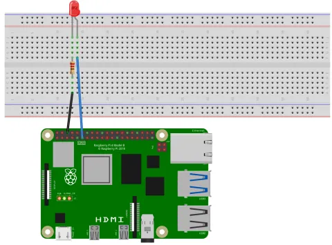
Section titled “The Circuit”Below we can see the circuit diagram for this project. We have the anode (longer wire) of the LED connected to GPIO Pin 11, while the cathode (shorter wire) is connected to ground pin 6 through a resistor.
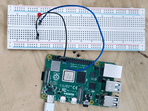
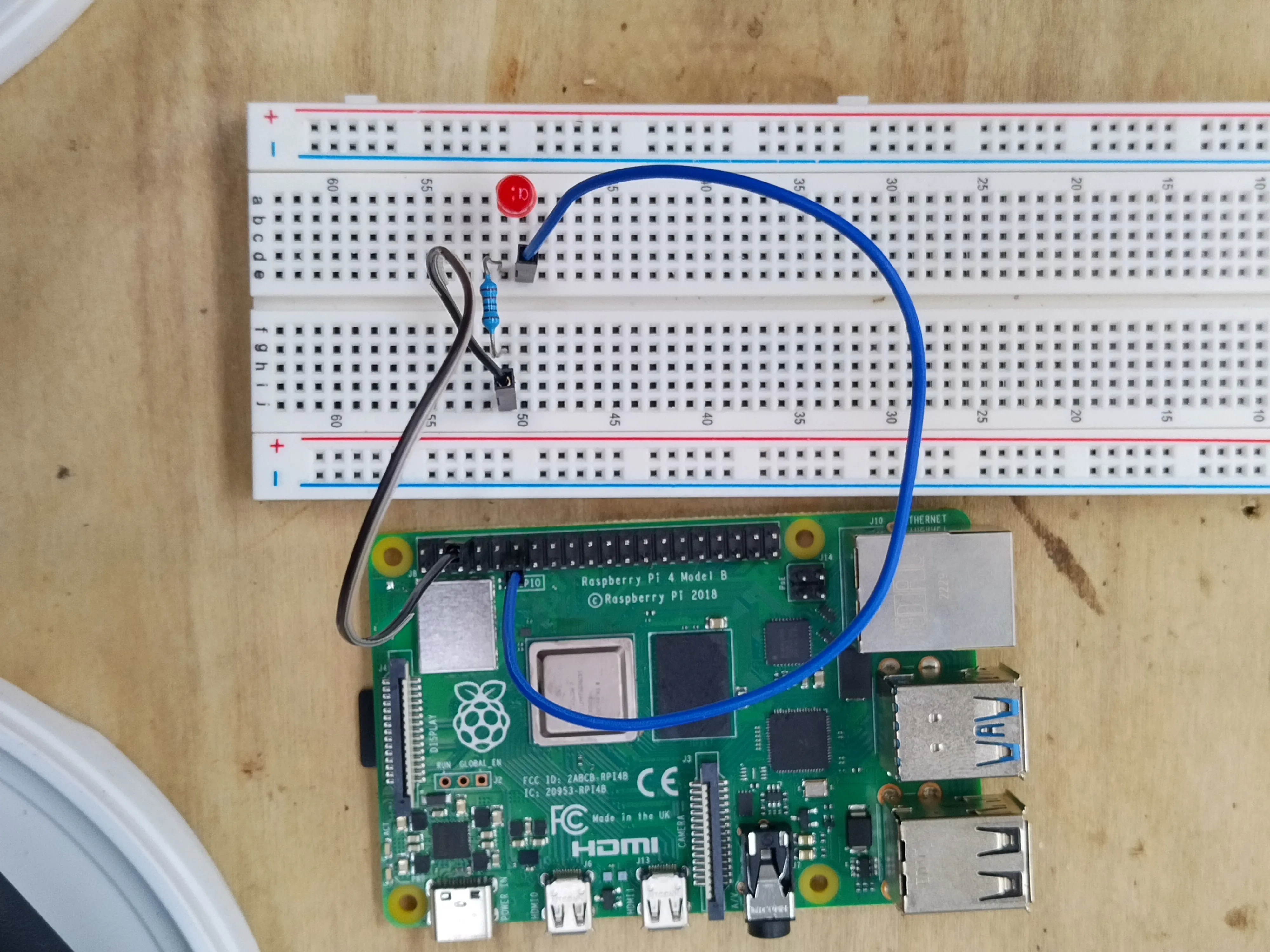
And the physical circuit looks like the following image, in which we’ve connected an M/F jumper wire from Pin 11 to the cathode of the LED. The anode of the LED is connected to the resistor, which is then connected to the ground pin through another M/F jumper wire.
Starting the Daemon
Section titled “Starting the Daemon”Underneath SplashKit we use the Pigpio library, specifically its daemon. To interface with this daemon, it must be running. If it is not running we can expect some output like the following:
gpio_init() must be called before any other GPIO functionsor
ERROR [default] Pigpio error: bad connect.We can check if its running by using the following command:
ps aux | grep pigpiodIf the daemon is not running, we can start it by using:
sudo pigpiodTo stop the daemon from running we can use the command:
sudo killall pigpiodThe Code
Section titled “The Code”After the daemon is running, we can then create our program. Below is an example program that blinks an LED on and off.
#include "splashkit.h"
int main(){    raspi_init();    gpio_pin led_pin = PIN_11;    raspi_set_mode(led_pin, GPIO_OUTPUT);
    open_window("dummy_window", 1, 1);    while(!any_key_pressed())    {        process_events();        raspi_write(led_pin, GPIO_HIGH);        delay(500);        raspi_write(led_pin, GPIO_LOW);        delay(500);    }
close_all_windows(); raspi_cleanup(); return 0;}using SplashKitSDK;using static SplashKitSDK.SplashKit;
RaspiInit();GpioPin ledPin = (GpioPin) 11;RaspiSetMode(ledPin, (GpioPinMode) 1);
OpenWindow("dummy_window", 1, 1);while(!AnyKeyPressed()){ ProcessEvents(); RaspiWrite(ledPin, (GpioPinValue) 1); Delay(500); RaspiWrite(ledPin, (GpioPinValue) 0); Delay(500);}
CloseAllWindows();RaspiCleanup();using SplashKitSDK;
namespace RaspberryPiBlinkingLED{ public class Program { public static void Main() { SplashKit.RaspiInit(); GpioPin ledPin = GpioPin.Pin11; SplashKit.RaspiSetMode(ledPin, GpioPinMode.GpioOutput);
SplashKit.OpenWindow("dummy_window", 1, 1); while (!SplashKit.AnyKeyPressed()) { SplashKit.ProcessEvents(); SplashKit.RaspiWrite(ledPin, GpioPinValue.GpioHigh); SplashKit.Delay(500); SplashKit.RaspiWrite(ledPin, GpioPinValue.GpioLow); SplashKit.Delay(500); }
SplashKit.CloseAllWindows(); SplashKit.RaspiCleanup(); } }}Understanding the code
Section titled “Understanding the code”To understand this code better, lets break it down and explore each section.
-
Initialise GPIO Hardware:
In this bit of the code we’re setting up the hardware, we call Raspi Init to initialise the GPIO pins, and then we define the specific pin we’re using which is Pin 11 in this case and it is of the Gpio Pin type.
We pass this value to Raspi Set Mode along with
GPIO_OUTPUTwhich sets the pin to be ready to output a signal on our command. TheGPIO_OUTPUTvalue is one of the Gpio Pin Modes that can be set. Each pin has alternative modes but we are only interested in the output mode for now.#include "splashkit.h"int main(){raspi_init();gpio_pin led_pin = PIN_11;raspi_set_mode(led_pin, GPIO_OUTPUT);open_window("dummy_window", 1, 1);while(!any_key_pressed()){process_events();raspi_write(led_pin, GPIO_HIGH);delay(500);raspi_write(led_pin, GPIO_LOW);delay(500);}close_all_windows();raspi_cleanup();return 0;}using SplashKitSDK;using static SplashKitSDK.SplashKit;RaspiInit();GpioPin ledPin = (GpioPin) 11;RaspiSetMode(ledPin, (GpioPinMode) 1);OpenWindow("dummy_window", 1, 1);while(!AnyKeyPressed()){ProcessEvents();RaspiWrite(ledPin, (GpioPinValue) 1);Delay(500);RaspiWrite(ledPin, (GpioPinValue) 0);Delay(500);}CloseAllWindows();RaspiCleanup();using SplashKitSDK;namespace RaspberryPiBlinkingLED{public class Program{public static void Main(){SplashKit.RaspiInit();GpioPin ledPin = GpioPin.Pin11;SplashKit.RaspiSetMode(ledPin, GpioPinMode.GpioOutput);SplashKit.OpenWindow("dummy_window", 1, 1);while (!SplashKit.AnyKeyPressed()){SplashKit.ProcessEvents();SplashKit.RaspiWrite(ledPin, GpioPinValue.GpioHigh);SplashKit.Delay(500);SplashKit.RaspiWrite(ledPin, GpioPinValue.GpioLow);SplashKit.Delay(500);}SplashKit.CloseAllWindows();SplashKit.RaspiCleanup();}}} -
Get User Inputs:
There is a small trick we can use to recognise keyboard inputs by opening a dummy window using Open Window, which initialises the backend so that we can detect input. We’ll then use a loop that runs while Any Key Pressed returns false. We use Process Events at the start of the loop to actually detect any user input. We can now press a key to end the program and ensure we cleanup correctly.
#include "splashkit.h"int main(){raspi_init();gpio_pin led_pin = PIN_11;raspi_set_mode(led_pin, GPIO_OUTPUT);open_window("dummy_window", 1, 1);while(!any_key_pressed()){process_events();raspi_write(led_pin, GPIO_HIGH);delay(500);raspi_write(led_pin, GPIO_LOW);delay(500);}close_all_windows();raspi_cleanup();return 0;}using SplashKitSDK;using static SplashKitSDK.SplashKit;RaspiInit();GpioPin ledPin = (GpioPin) 11;RaspiSetMode(ledPin, (GpioPinMode) 1);OpenWindow("dummy_window", 1, 1);while(!AnyKeyPressed()){ProcessEvents();RaspiWrite(ledPin, (GpioPinValue) 1);Delay(500);RaspiWrite(ledPin, (GpioPinValue) 0);Delay(500);}CloseAllWindows();RaspiCleanup();using SplashKitSDK;namespace RaspberryPiBlinkingLED{public class Program{public static void Main(){SplashKit.RaspiInit();GpioPin ledPin = GpioPin.Pin11;SplashKit.RaspiSetMode(ledPin, GpioPinMode.GpioOutput);SplashKit.OpenWindow("dummy_window", 1, 1);while (!SplashKit.AnyKeyPressed()){SplashKit.ProcessEvents();SplashKit.RaspiWrite(ledPin, GpioPinValue.GpioHigh);SplashKit.Delay(500);SplashKit.RaspiWrite(ledPin, GpioPinValue.GpioLow);SplashKit.Delay(500);}SplashKit.CloseAllWindows();SplashKit.RaspiCleanup();}}} -
Blink the LED:
Now that we’ve setup our pins and defined our end condition, we can now manipulate the LED. Inside the while loop we first use Raspi Write to change the output of our pin to
GPIO_HIGH, one of the Pin Values. Doing this provides electricity to the LED and turn it on. We then wait for half a second using Delay. Then we turn our LED off using Raspi Write, but now we useGPIO_LOW, and wait for another half-second.#include "splashkit.h"int main(){raspi_init();gpio_pin led_pin = PIN_11;raspi_set_mode(led_pin, GPIO_OUTPUT);open_window("dummy_window", 1, 1);while(!any_key_pressed()){process_events();raspi_write(led_pin, GPIO_HIGH);delay(500);raspi_write(led_pin, GPIO_LOW);delay(500);}close_all_windows();raspi_cleanup();return 0;}using SplashKitSDK;using static SplashKitSDK.SplashKit;RaspiInit();GpioPin ledPin = (GpioPin) 11;RaspiSetMode(ledPin, (GpioPinMode) 1);OpenWindow("dummy_window", 1, 1);while(!AnyKeyPressed()){ProcessEvents();RaspiWrite(ledPin, (GpioPinValue) 1);Delay(500);RaspiWrite(ledPin, (GpioPinValue) 0);Delay(500);}CloseAllWindows();RaspiCleanup();using SplashKitSDK;namespace RaspberryPiBlinkingLED{public class Program{public static void Main(){SplashKit.RaspiInit();GpioPin ledPin = GpioPin.Pin11;SplashKit.RaspiSetMode(ledPin, GpioPinMode.GpioOutput);SplashKit.OpenWindow("dummy_window", 1, 1);while (!SplashKit.AnyKeyPressed()){SplashKit.ProcessEvents();SplashKit.RaspiWrite(ledPin, GpioPinValue.GpioHigh);SplashKit.Delay(500);SplashKit.RaspiWrite(ledPin, GpioPinValue.GpioLow);SplashKit.Delay(500);}SplashKit.CloseAllWindows();SplashKit.RaspiCleanup();}}} -
Clean Up Memory:
Finally, as we exit the program we must ensure that we cleanup our program properly. We must first close the dummy window we opened use Close All Windows. We then call Raspi Cleanup to ensure our pins are turned off and cleaned.
#include "splashkit.h"int main(){raspi_init();gpio_pin led_pin = PIN_11;raspi_set_mode(led_pin, GPIO_OUTPUT);open_window("dummy_window", 1, 1);while(!any_key_pressed()){process_events();raspi_write(led_pin, GPIO_HIGH);delay(500);raspi_write(led_pin, GPIO_LOW);delay(500);}close_all_windows();raspi_cleanup();return 0;}using SplashKitSDK;using static SplashKitSDK.SplashKit;RaspiInit();GpioPin ledPin = (GpioPin) 11;RaspiSetMode(ledPin, (GpioPinMode) 1);OpenWindow("dummy_window", 1, 1);while(!AnyKeyPressed()){ProcessEvents();RaspiWrite(ledPin, (GpioPinValue) 1);Delay(500);RaspiWrite(ledPin, (GpioPinValue) 0);Delay(500);}CloseAllWindows();RaspiCleanup();using SplashKitSDK;namespace RaspberryPiBlinkingLED{public class Program{public static void Main(){SplashKit.RaspiInit();GpioPin ledPin = GpioPin.Pin11;SplashKit.RaspiSetMode(ledPin, GpioPinMode.GpioOutput);SplashKit.OpenWindow("dummy_window", 1, 1);while (!SplashKit.AnyKeyPressed()){SplashKit.ProcessEvents();SplashKit.RaspiWrite(ledPin, GpioPinValue.GpioHigh);SplashKit.Delay(500);SplashKit.RaspiWrite(ledPin, GpioPinValue.GpioLow);SplashKit.Delay(500);}SplashKit.CloseAllWindows();SplashKit.RaspiCleanup();}}}
Build and run the code
Section titled “Build and run the code”We can build this program with the following command:
g++ led_blink.cpp -l SplashKit -o led_blinkdotnet buildThen we run the program with the following command:
./led_blinkdotnet runThis code blinks the LED on and off as you can see below. This continues until the 10 seconds has elapsed, and after we exit the while loop, Raspi Cleanup is called and the GPIO pins are reset.